Friday, May 3, 2024

Cracking the Code: PHR vs Toyota Thermostat Activation Events and Accuracy

 In the world of high-performance racing, every detail counts towards achieving victory on the track. From engine tuning to aerodynamics, each component plays a crucial role in determining the overall performance of a race car. Among these components, the thermostat stands as a silent yet essential regulator of engine temperature. In this analytical blog post, we'll delve into a comparative analysis of thermostats from Powerhouse Racing (PHR) and the factory Toyota counterpart, shedding light on their efficiency and significance in racing applications.

Optimizing Racing Performance: The thermostat is just one piece of the puzzle in optimizing racing performance. When combined with other well-designed cooling system components, it contributes to a finely-tuned racing machine capable of delivering peak performance on the track. By investing in high-quality products like those offered by Powerhouse Racing, racers can gain a competitive edge and push the limits with confidence.

Understanding The Thermostat: Thermostat temperature range is crucial for maintaining optimal engine temperature, which directly impacts performance and reliability, especially in racing conditions. A well-designed thermostat should spend most of its time regulating temperature within a specific range, responding dynamically to changes in engine load and ambient conditions. 

It is important to understand the function of the thermostat: to REGULATE coolant flow through the radiator. It does NOT aid in cooling, nor does it increase thermal efficiency. Further, it certainly cannot stop a car from overheating if the cooling system is inadequate. That being said a, failed thermostat certainly can be the cause of overheating, if it stuck in a closed or nearly closed position.

The thermostat should be though of in these terms: At what temperature range do I want my car to operate. As stated, the thermostats job is to regulate the flow through the radiator and therefore its range is where this flow will be regulated.

Importance of Efficient Cooling Systems: In a racing application, where precision and reliability are paramount, the efficiency of the cooling system can make or break performance. A well-designed cooling system, comprising components like radiators, intercoolers, water pumps, and cooling fans from reputable manufacturers like Powerhouse Racing, ensures consistent engine temperature regulation and optimal performance throughout races. Without an efficient cooling system to work with it, the thermostat will act simply as a valve that opens at a specific temperature, and then is meaningless as the temperature continues to rise above the range.

This is why PHR offers several different thermostat options so you can select your specific operating temperature range rather than just a single performance thermostat.

Target Temperature: Target temperature is controlled by a combination of the thermostat and the cooling fan. This is only meaningful if you have a system efficient enough to be capable of maintaining that target. As an example, if your thermostat's temperature range is 160 degrees to 180 degrees, and your fan is at full speed, but your coolant temperature is at 200 degrees, this would indicate a cooling system that is inadequate for the thermostats temperature range. 

The target temperature is like fine tuning within that range. This is controlled either electronically with electric fans, or mechanically with the fan clutch on a mechanical fan setup like the factory Supra setup. The fan clutch is not a precise device. It tightens as temperature increases and loosens as temperature decreases and therefore acts a lot like the thermostat, maintaining a range rather than a specific target. Whereas a good electric fan setup can target a very specific temperature. We delve more into this in our blog post, Importance of efficient cooling systems and target temperature.

Understanding the Terminology: Before we dive into the comparison, let's clarify some key terms. The "crack temperature" refers to the moment when the thermostat begins to open, akin to a door "cracking" open. This is also the temperature rating that is stamped in the thermostat and is how the automotive industry classifies the opening temperature. Meanwhile, the "full open temperature" marks the point at which the thermostat is fully open, allowing optimal coolant flow.


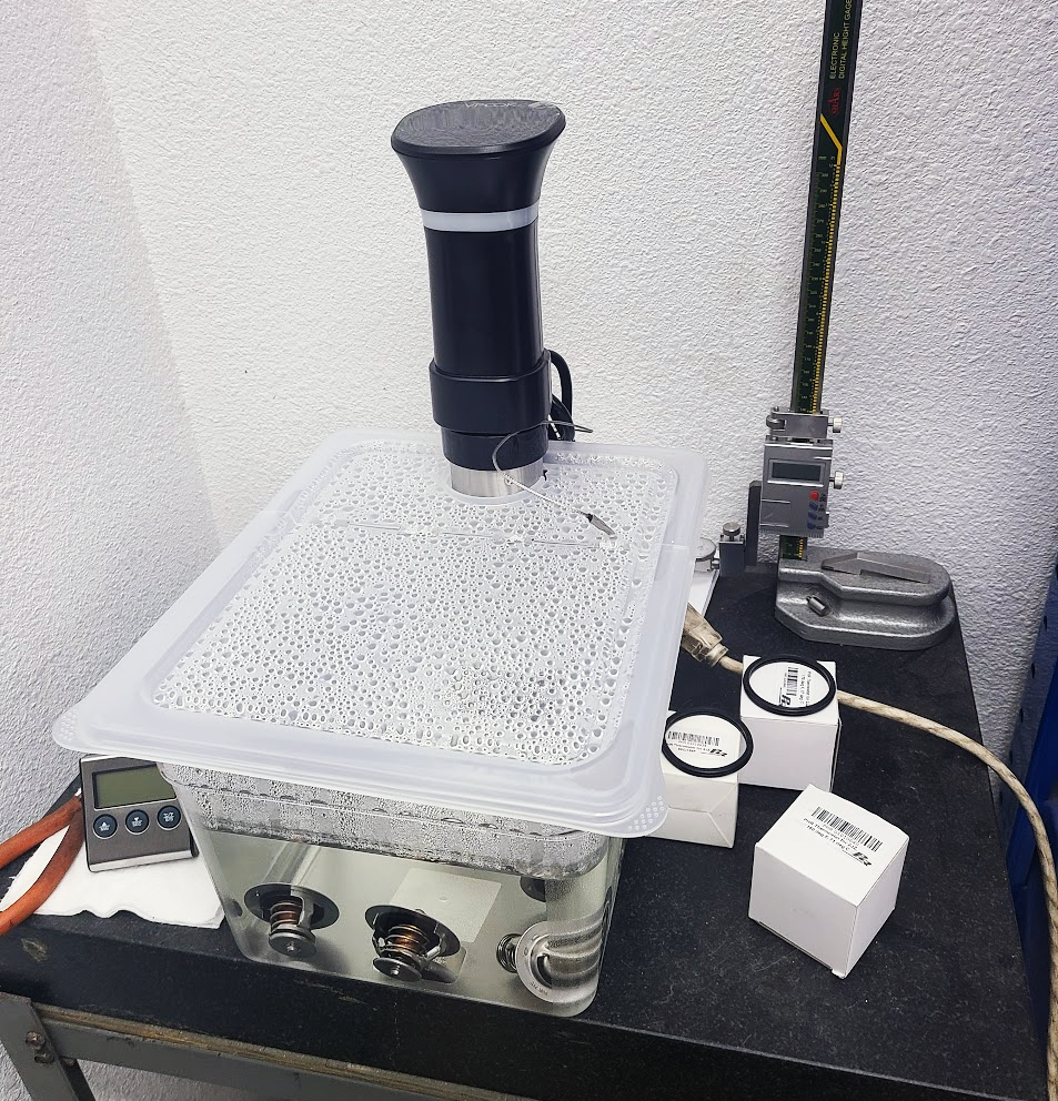
Comparative Analysis: Powerhouse Racing vs. Factory Toyota: To understand the impact of thermostat efficiency, we've conducted tests on three Powerhouse Racing thermostats alongside the factory Toyota thermostat. Let's examine the results:

Image of Powerhouse 68 Degree Thermostat

Powerhouse

68°C/155°F

Image of Powerhouse 71 Degree Thermostat

 Powerhouse

71°C/160°F


Image of Powerhouse 77 Degree Thermostat

 Powerhouse

77°C/170°F

Image of Toyota 82 Degree Thermostat

 Toyota

82°C/180°F

  1. Powerhouse 68°C/155°F Thermostat: Crack Temperature: 68.5°C/155.3°F, Full Open Temperature: 81.6°C/179.0°F
  2. Powerhouse 71°C/160°F Thermostat: Crack Temperature: 71.2°C/160.2°F, Full Open Temperature: 85.1°C/185.1°F
  3. Powerhouse 77°C/170°F Thermostat: Crack Temperature: 77.2°C/170.9°F, Full Open Temperature: 90.2°C/194.4°F
  4. Factory Toyota 82°C/180°F Thermostat: Crack Temperature: 82.9°C/181.3°F, Full Open Temperature: 93.7°C/200.6°F

Analyzing Test Results: Comparing the crack temperatures of the Powerhouse Racing thermostats to the factory Toyota thermostat reveals significant differences. The Powerhouse Racing thermostats exhibit lower crack temperatures, indicating lower temperature activation. Additionally, their lower full open temperatures suggest lower peak temperature target for varying conditions.

Conclusion: In conclusion, the crack and full open temperatures of thermostats plays a critical role in maintaining optimal engine temperature and maximizing racing performance. Through simple testing and analysis, we've highlighted the difference of Powerhouse Racing thermostats in terms of activation and temperature regulation. When integrated into a well-designed cooling system, these thermostats contribute to a winning formula for success on the racetrack.

Upgrade your racing experience with precision-engineered cooling system components and unlock the full potential of your race car. Explore Powerhouse Racing's product lineup today and elevate your racing performance to new heights.

Powerhouse Racing creates racing parts for cooling systems. Here are links to the the cooling system categories for specific vehicles:
MKIV Toyota Supra Turbo
MKIV Toyota Supra NA
Lexus IS300
Lexus GS300
Lexus SC300

Friday, April 26, 2024

How to install a reverse mount master cylinder. Featuring the PHR Reverse Mount Dual Brake Master Cylinder Kit for Nissan S14 240SX

 Links to the products featured on this post:

PHR Reverse Mount Dual Master Cylinder Kit for S14 240SX

Step 1

To do this you, obviously the dash needs to be removed from the car. Remove the dash, wiring, brake master cylinder, brake booster, pedal assembly, and any other things that might be in the way of doing the next steps. You really need to have the entire dash area pretty much empty.

You need to remove the large sheet metal bracket on the left-hand side of the steering column that holds the steering column up.


In the picture above you can see where the roll cage dash bar is. It might be necessary to move your dash bar to a different location or height to accommodate the master cylinder kit if you already have a roll cage installed.

 Make sure the steering column is lowered and no longer connected to the bracket. 


Drill out the spot welds on the sheet metal bracket. The lower ones can be accessed from inside the cowl where the wiper assembly is located. You’ll need to access the cowl area by removing the wipers and plastic covering. You can identify where the spot welds are by the indentations in the sheet metal. A ¼ inch drill bit usually does the trick, but if it doesn’t fully separate, increase the drill bit size until the weld is drilled completely out. This will leave holes remaining in the sheet metal and these will have to be filled in with a sealant or welded back closed to prevent leaking.

See pictures below:

Step 2

Insert the spacers into the rolled sheet metal where the brake booster used to mount. They should slide in with some ease, but it is often the case that the rolled sheet metal will need to be pried open a little to accommodate the spacer. Loose is better than tight because you don’t want to spacer forcing the screws that will bolt the assembly in place to be forced into misalignment. Opening the rolled sheet metal can be done with a screw driver.

Step 3

Assemble the brake master cylinders and mount onto the brake master cylinder bracket using the main,  top, and lower brackets.

Step 4

Adjust the master cylinder rods so the the pedal will have it’s needed amount of throw without hitting the main bracket. Having the rods extended allows the pedal to come up off the floor when installed and allow the brake switch to be depressed when up all the way. If you don’t extend the rods, the pedal might not lift off the floor enough and could cause the pedal to hit the floor when fully depressed. However, you don’t want the rods extended too much to hit the bracket.

Consult the Wilwood instructions for adjusting the bias bar. You can preset the bar, but to adjust, it might be necessary to remove the assembly or remove the dash again to to fine tune the brakes.  Completely read the Wilwood instructions to understand the functionality of the system.

Step 5

Set the firewall block-off plate in place using the 4 counter sink screws. These will not tight yet. They just allow everything to rest in place.

Step 6

Have an assistant help hold the assembly in place while the firewall block-off nuts are tightened. Be careful not to cross thread the screws. 

Bolt the upper bracket into it’s sheet metal location as well.

Step 7

Bolt the steering column to the steering column bracket on the car and the steering column bracket attached to the brake master cylinder bracket.


To set the brake pedal switch, it is ok to bend the brake switch bracket a little to accommodate the pedal throw.


The bracket installation is now complete.

 -------------------------------------------------------------------------------------------------------------------------------------

The reservoirs can be install in a number of different locations, they can be kept under the dash or mounted inside the engine bay or in the cowl. You must make sure the reservoirs are higher than the inlets to the master cylinders.

Here is an installation of the master cylinders in the cowl. Mounting in the cowl required trimming the plastic brackets and trimming the cowl plastic to accommodate the master cylinders.


Step 1

Mark and trim area where reservoirs will mount. Note: where located in the picture, it had barely enough room for the hose off the bottom of the reservoir to clear the master cylinder assembly. You need to make sure the reservoirs are over far enough to not cause a conflict:

Step 2

Mark and drill holes where hoses will need to run. Make sure holes are large enough that the hoses can pass through without rubbing on the edges. Keep in mind that if you use this method, there is no way to seal the cowl off from the interior of the car unless you add a grommet around the hose sealing off the hole that was drilled.


Step 3

Mark and drill holes in firewall to mount the reservoirs.


Step 4

Clamp the reservoirs to their brackets and attach hose to barb. Note how this bracket is trimmed to allow the reservoir to mount as low in the cowl as possible. Even with it trimmed down, it will still be high enough to stick up through the cowl plastic.

Step 5

Run the hoses through their holes and mount the reservoirs to the firewall.


Step 6

Trim the hose to length, attach the hose to the barbs on master cylinder adapters and clamp the adapters to the master cylinders.


Make sure hoses cannot interfere with the master cylinder operation. This is extremely important!!

Besides these steps, with the reservoirs as high as they are, the plastic will need to be trimmed around the lids. Be careful when installing the hood that it can fully close without hitting the reservoirs and trim the bottom of the hood if necessary.

Keep in mind, when bleeding the master cylinders, this mount position or other mount positions might make the hoses have a high point in them that can trap air. This is usually very simple to bleed out, but care must be taken that all air is removed from the system. Sometime a rapid reverse bleed can force any trapped air out. This is not normally a problem and bleeding mostly very straight forward with the air moving down the line like it is supposed to, but you should keep in mind that it is possible to get air trapped and you should be very careful to make sure your system is set up and bled completely.

You need to consult the Wilwood technical documentation for proper master cylinder sizing, balance bar adjustment and brake pressure measurements. Wilwood is the proper source for brake technical help and these instructions are just here for installation of the bracket and not a good source for brake system functionality or adjustments.